Your Shopping Cart
SKU: UAX-90050-01
$895On sale price $806
Primary Features
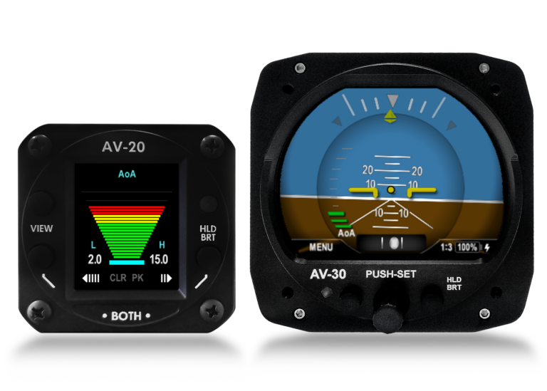
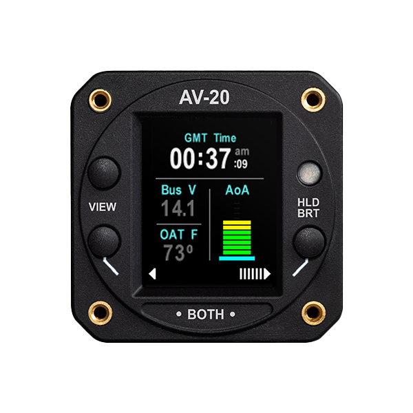
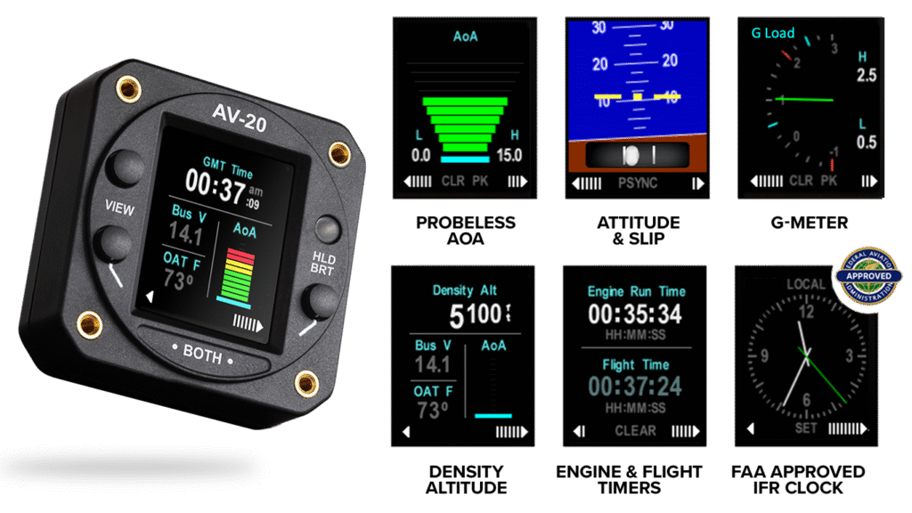
AV-20 is available for certified and experimental aircraft as a NORSEE certfied clock replacement that puts 12 functions at your fingertips. From Flight and Engine timers to bus voltage and Audible AoA / G-limit alerts, it’s the perfect, no compromise upgrade to your panel.
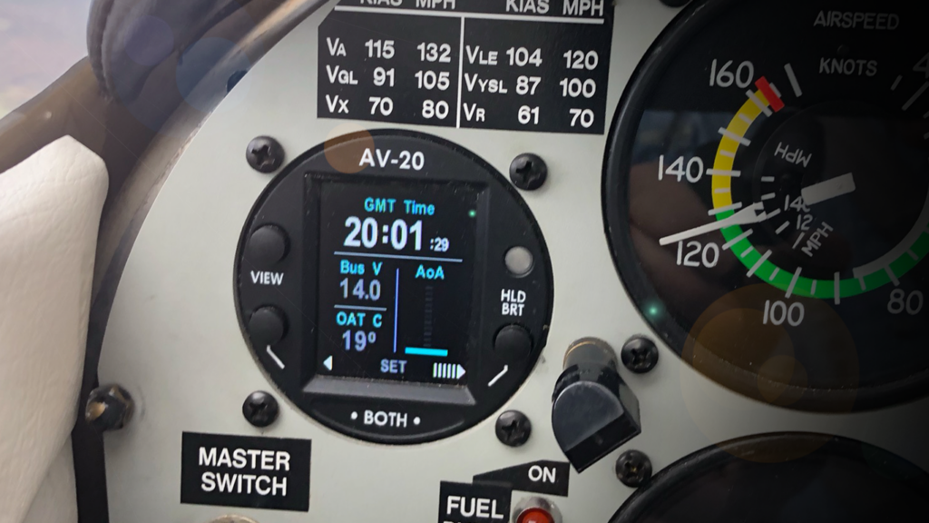
With a matte display, the AV-20 is visible in direct sunlight and automatically adjusts brightness to ambient light giving the clarity you need at a glance.
Fly focused and aware with customizable audio alerts. The AV-20’s multiple display configurations provide audio triggers to alert you of critical flight information and keep you safe.

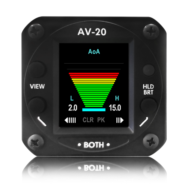
The AV-20 alerts you visually and aurally if you approach a dangerous AoA during critical phases of flight such as landing approach. AoA is a derived calculation determined by comparing the aircraft’s pitch, flight path, and G-loading.
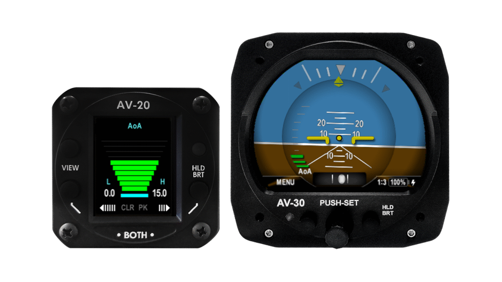
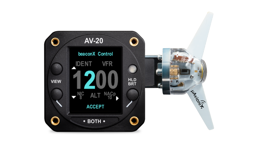
The tailBeaconX TSO + AV-20-E Bundle combines the groundbreaking innovation of the tailBeaconX with the control head functions of the AV-20-E to provide experimental aircraft global ADS-B compliance and multiple functions all in a compact, easy to install package
Additional Features
Fully certified to meet FAA standards, ensuring reliability and compliance with aviation safety regulations. AV-20-S is also an FAA-Approved clock for both VFR and IFR aircraft.
The AV-20 alerts you visually and aurally if you approach a dangerous AoA during critical phases of flight such as landing approach.
Includes a backup power source that ensures functionality and timekeeping even during power interruptions.
Bundles
Packages
FAQ’S
The AV-20-S is suitable for installation in Part 23 Class I and II aircraft as outlined in its NORSEE certification.
Yes, the AV-20-S is FAA approved under the NORSEE (Non-Required Safety Enhancing Equipment) policy, ensuring it meets high safety and performance standards.
The AV-20-S is designed for easy installation in a standard 2” instrument hole, with minimal aircraft modification required. Detailed installation guidelines are provided in the AV-20 Installation Manual.
The AV-20-S features a user-friendly interface that allows pilots to customize display settings including brightness, audio alerts, and more directly through the unit’s setup menu.
Regular maintenance includes checking the internal battery and ensuring that the software is updated. Refer to the Pilot’s Guide for detailed maintenance instructions.
Ensure the unit is properly calibrated, especially for AoA and G-meter functionalities. If issues persist, consult the Troubleshooting section of the Pilot’s Guide or contact uAvionix support for assistance.
Documentation
| Specification | Value |
|---|---|
| Input Voltage Nominal | +10 to +32 VDC |
| Input Voltage Max | +60 VDC |
| Input Power Nominal | 3 Watts (0.25Amps @ 12VDC) |
| Input Power Max | 6 Watts (0.50 Amps @ 12VDC) |
| Required Circuit Breaker | 1 Amp |
| Operation on Battery | 30 Minutes (Standard 15°C Env) |
| Physical Attributes | |
| Mounting Configuration | 2 ¼” Round Instrument Hole |
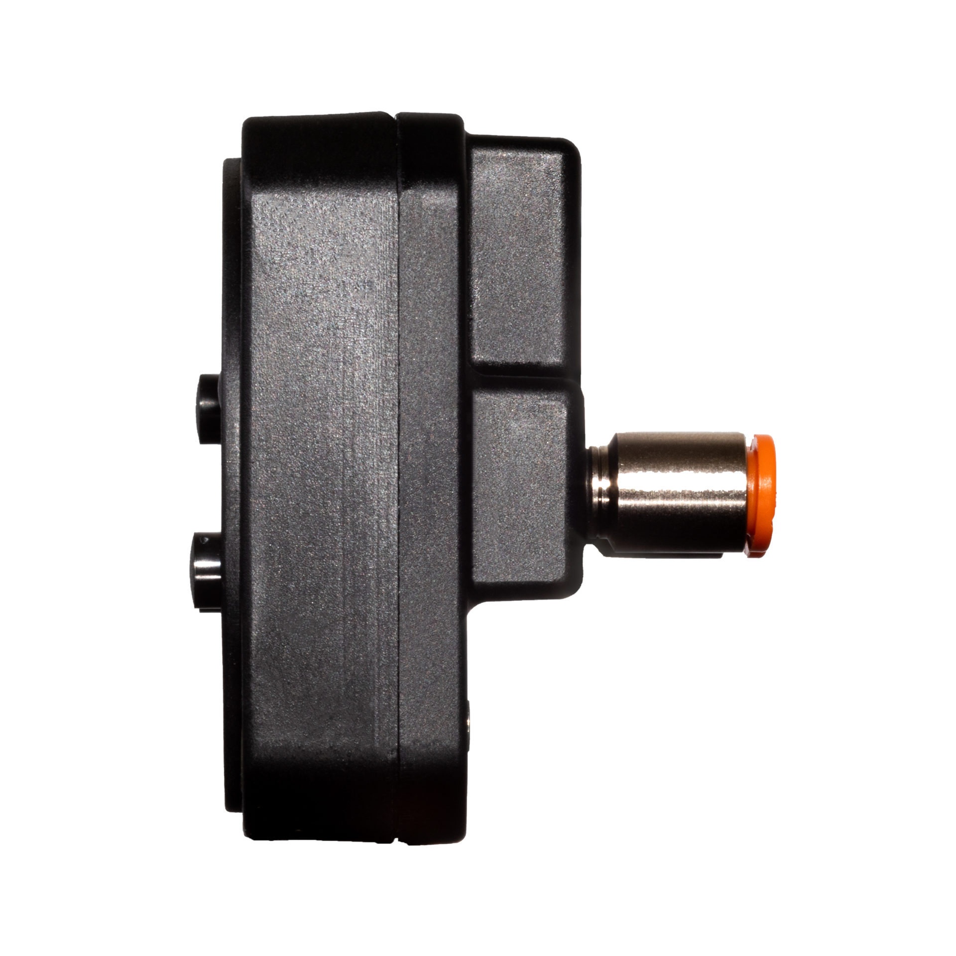
| Dimensions wo/Connector | 2.4 x 2.4 x 1.2 Inches |
| Weight | 0.25 Lbs. |
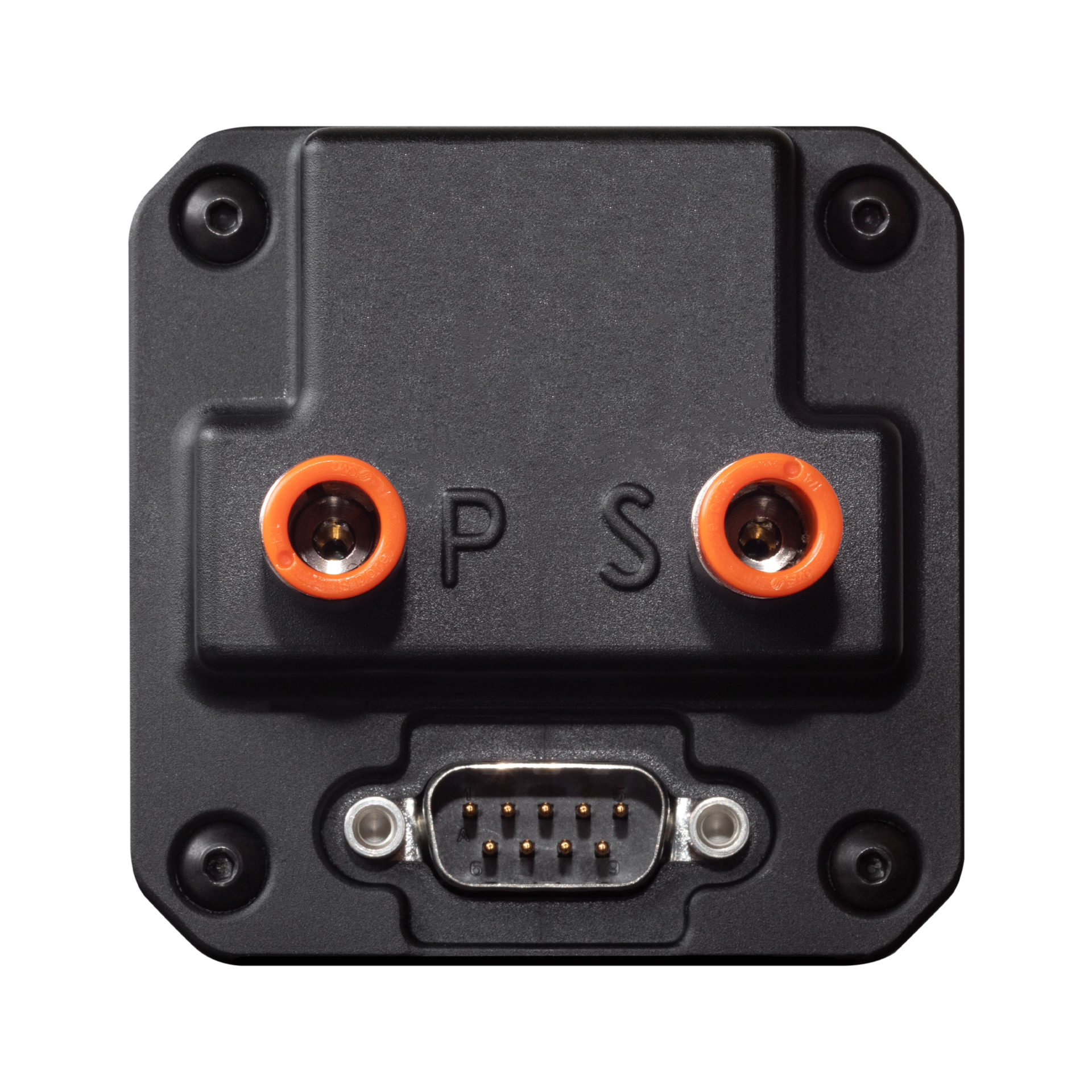
| Electrical Connector | 9 Pin Male D-Sub |
| Pneumatic Connectors | ¼” OD Quick Connect |
| Mounting | (4X) #6-32 Machine Screws |
| Case Material | High Impact ABS Plastic |
| Environmental | |
| Operating Temp | -20°C to +55°C |
| Storage Temp (48 Hrs) | -30°C to +80°C (Via Analysis) |
| Humidity (48 Hrs) | 90% RH (Via Analysis) |
| Display | |
| Diagonal Size | 1.8” |
| Contrast Ratio (Typical) | 500 |
| Brightness (Typical) | 1000 cd/m2 |
| Viewing Angle Left/Right | 60° |
| Viewing Angle Up | 45° |
| Viewing Angle Down | 10° |
| Backlight Lifetime (Typical) | 50,000 Hrs |
Resources
Documentation