Your Shopping Cart
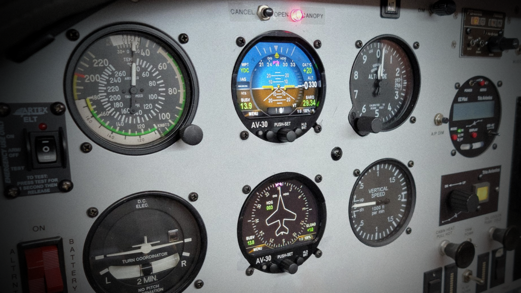
AV-30-C
SKU: UAX-90052-01
$2,499
Features
The perfect fit for your aircraft – Replace Analog Gauges with Full Featured Digital displays
Customizable Display Modes
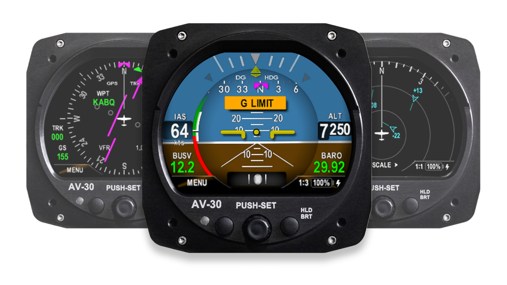
The AV-30 comes standard out of the box with 4 modes (AI, DG, MFD, CDI/HSI and over 14 functions. The AV-HSI and AV-APA modules enable connection with your existing cockpit instruments for IFR flying and autopilot integration.
Control Everything from One Place
Reduce your workload and easily switch between different flight data layouts and personalize information views.
Enhanced Pilot Awareness
The AV-30 alerts you visually and aurally if you approach a dangerous AoA. AoA is calculated by comparing the aircraft’s pitch, flight path, and G-loading.
Primary Features
-
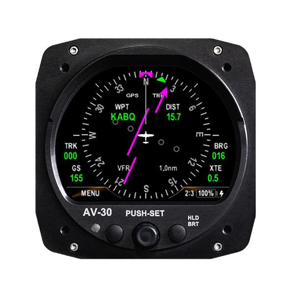
All-in-One Digital Flight Display
Combines attitude, heading, airspeed, altitude, slip, and more in a single, easy-to-read unit. The AV-30’s multifunction customizable display is configurable for each phase of your flight.
-
Advanced Connectivity & Functionality with AV-Link
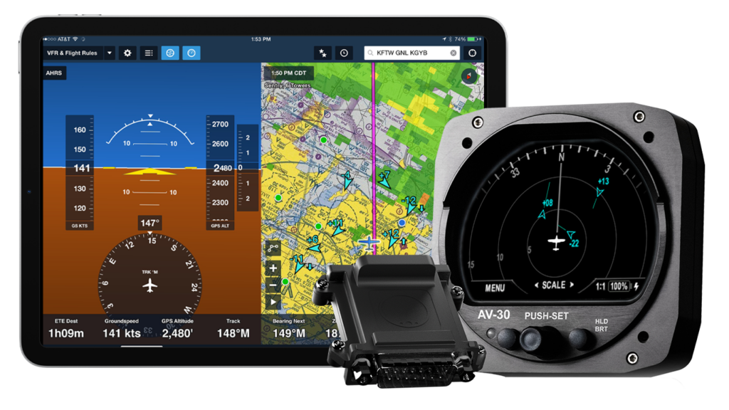
Unlock live ADS-B traffic display, Wi-Fi firmware updates, and future enhancements with the optional AV-Link module.
-
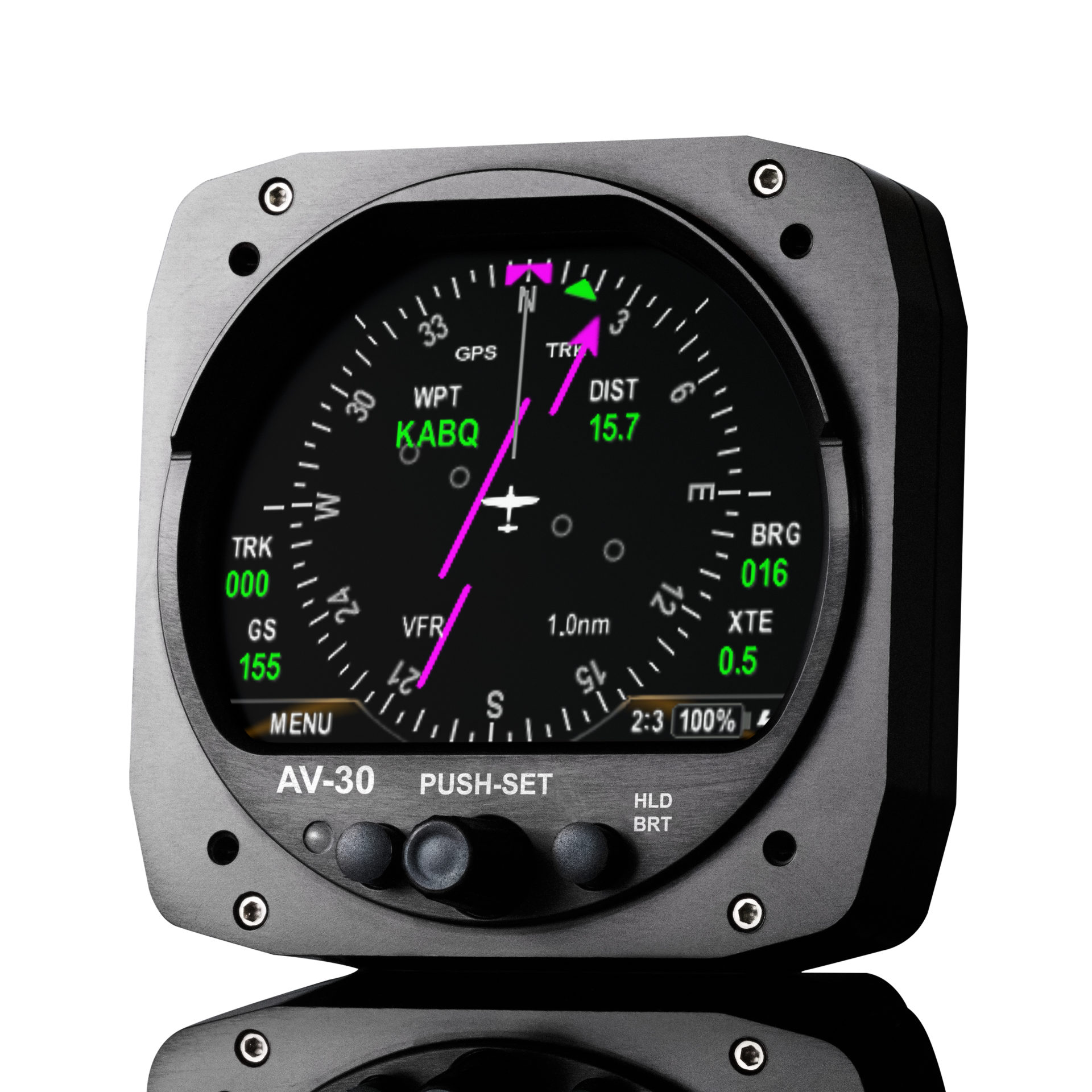
Preserves Classic Round-Gauge Aesthetic
Modern avionics with a vintage look, seamlessly fitting into existing 3-inch instrument slots with no cutting required, saving you time and money while modernizing your aircraft.
1 / 3
Bundles
You’re In Control with the AV-30
The AV-30 serves as the control head for the tailBeaconX TSO and echoESX EXP Mode S ADS-B Transponders. Save more when you bundle them together to get a cockpit upgrade and the best in ADS-B Out compliance.

Packages
AV-30 Traffic Display Solution
Easily display ADS-B traffic center stage on the AV-30-C MFD. When combined with the AV-Link PMA Wi-Fi module and the skySensor TSO ADS-B receiver with integrated GPS, you can wirelessly display nearby ADS-B traffic and select targets of interest to see flight details – all within your normal six pack scan
Fly with the ultimate awareness in any weather
It’s the best of both worlds – get the awareness and guidance you need to fly IFR with the AV-HSI and AV-Link WIFI modules. The AV-HSI seamlessly connects to you GPS Navigator or NAV/Comm radio for display of ILS and LPV guidance on your AV-30, while the AV-Link connects with your GDL-90 compliant ADS-B In receiver – think Sentry or skySensor! – and you have complete airspace and weather awareness. Have more than one AV-30? No problem, the AV-HSI can sync across multiple AV-30’s to let you focus on what matters most – flying!
AV-30 Accessories
Enhance Your Setup and Keep Flying
uAvionix makes a variety of add-on modules and accessories to enhance your flying experience and ensure you get the most from your AV-30. Check out the latest here!
AV-30-C Installation Kit
AV-30 Li-Ion (Lithium-Ion) Battery
FAQ’s
Knowledge Base
- All
- Aircraft
- FAA Requirements
- Installation
- Operation
- Maintenance
- Troubleshooting Tips and Tricks
- Software Update
-
-
What is the AV-30, and what are its key features?
The AV-30 is a versatile electronic flight instrument system (EFIS) that replaces traditional vacuum driven legacy instruments as your primary Attitude Indicator, Directional Gyro, Slip/Skid indicator, or simply a multifunctional display for your every need.
Key features include:
- Provides attitude, directional gyro (DG), angle of attack (AoA), ADS-B traffic and other key flight data
- Modern digital direct sunlight readable display
- Configurable for various aircraft, including flexible display configuration, panel placement, and functional assignment
More information can be found in the Pilot’s Guide. AV-30-C (Certified) & AV-30-E (Experimental)
-
What accessories are available for the AV-30?
Available accessories include:
- AV-Link: Enables live ADS-B traffic, wireless firmware updates, and future connectivity enhancements with ForeFlight
- AV-HSI: Enhances navigation capabilities by providing IFR approved Lateral and Vertical (glideslope) deviation for enroute and approaches. Also, integrates with Trio and TruTrak (Aerocruze) autopilots.
- AV-APA: Facilitates autopilot integration with Stec autopilots.
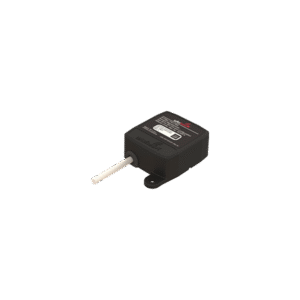
- AV-Mag: External magnetometer for heading correction every 200ms.
Please reference the AV-30 Pilot’s Guide and installation manual for more information on the accessories.
-
-
-
What is an AML, and how does it affect the AV-30 installation?
The AML (Approved Model List)
specifies the aircraft models approved for AV-30 installation under its STC. With hundreds of aircraft included, the AML makes the AV-30 a broadly compatible solution for upgrading avionics in certified aircraft. -
How do I verify if my aircraft is eligible for an AV-30 installation?
To confirm your aircraft model’s eligibility for the AV-30 installation
consult the AML List, which is regularly updated to encompass more aircraft models.
-
-
-
What are the differences between the certified and experimental versions?
The certified version (AV-30-C) is FAA-approved through a Supplemental Type Certificate (STC) and an Aircraft Model List (AML), while the experimental version is for non-certified aircraft. The STC, permission to use the STC in various countries and the AML are available in the Documentation section.
-
What is an STC, and how does it apply to the AV-30?
An STC (Supplemental Type Certificate) is an FAA approval for modifications to an aircraft’s design. The AV-30’s STC certifies its use as a replacement for a primary Attitude Indicator or Directional Gyro. The AV-30-C is installed under AML-STC #SA00410BO. Installation of the AV-30-C via the STC is required for use with the tailBeaconX. See the Documentation section for more information.
-
What are my options if my aircraft is not listed on the AML?
The current AV-30-C AML applies to Part 23 single-engine aircraft operating under 300kts. We have tried to include as many of the applicable aircraft as possible. If your aircraft is not listed on the AML but does fall within the AML limitations, you may be able to obtain a field approval from your local Flight Standards District Office (FSDO). We’re also interested in adding more aircraft to the AML. Please send us the model information and your request on a support ticket.
-
-
-
Can I install the AV-30 myself?
Installation requirements vary depending on the aircraft type:
Certified Aircraft: Professional installation by a certified Aviation Maintenance Technician is required. A 337 needs to be approved by an IA or certified avionics installer. uAvionix maintains a list of Preferred Installers
Experimental Aircraft: Consultation of a certified Aviation Maintenance Technician is recommended.
-
Can the AV-30 be installed as a primary instrument in certified aircraft?
Yes, the AV-30 can replace primary attitude indicators or directional gyros in aircraft listed in its AML. It is certified under its STC to meet technical and regulatory requirements, ensuring safe operation in the role of a primary flight instrument.
The AV-30-C is approved as a stand-alone attitude indicator, directional gyro (dual unit installation), and slip-skid indicator.
If the installation configuration leaves no instruments that require a vacuum source, the vacuum pump system may be removed from the aircraft by an A&P/IA or authorized facility. The procedure for removal of the vacuum system is aircraft specific and beyond the scope of the AV-30-C Installation and STC approval. This is normally found in the maintenance manual of the aircraft.
-
Where can I find detailed installation instructions for the AV-30-C?
Additional information is available in the Documentation section.
-
What is required for an AV-30-C installation?
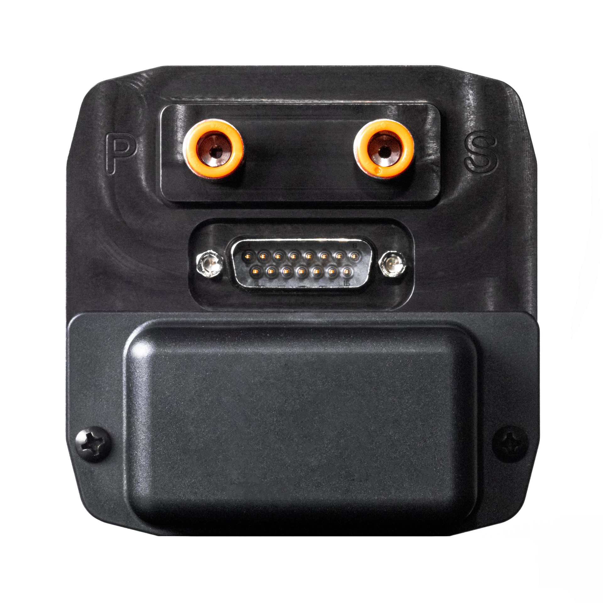
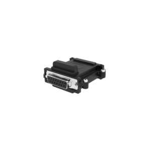
The AV-30-C holds an STC-PMA with AML. The installation must be performed by a licensed aircraft technician and a 337 must be submitted as part of the installation. The AV-30-C ships with the AV-30-C, DB-15 connector, DB crimps, and a backshell for the DB connector. The DB-15 connector needs to be populated with pins based on the functions desired for the specific installation. If the aircraft is IFR certified, the pitot/static system will need checked after the AV-30-C is added to the system according to 91.411(2).
-
-
-
What functions does the AV-30 panel display provide?
The AV-30 panel display offers a range of functions, including –
Primary Functions:
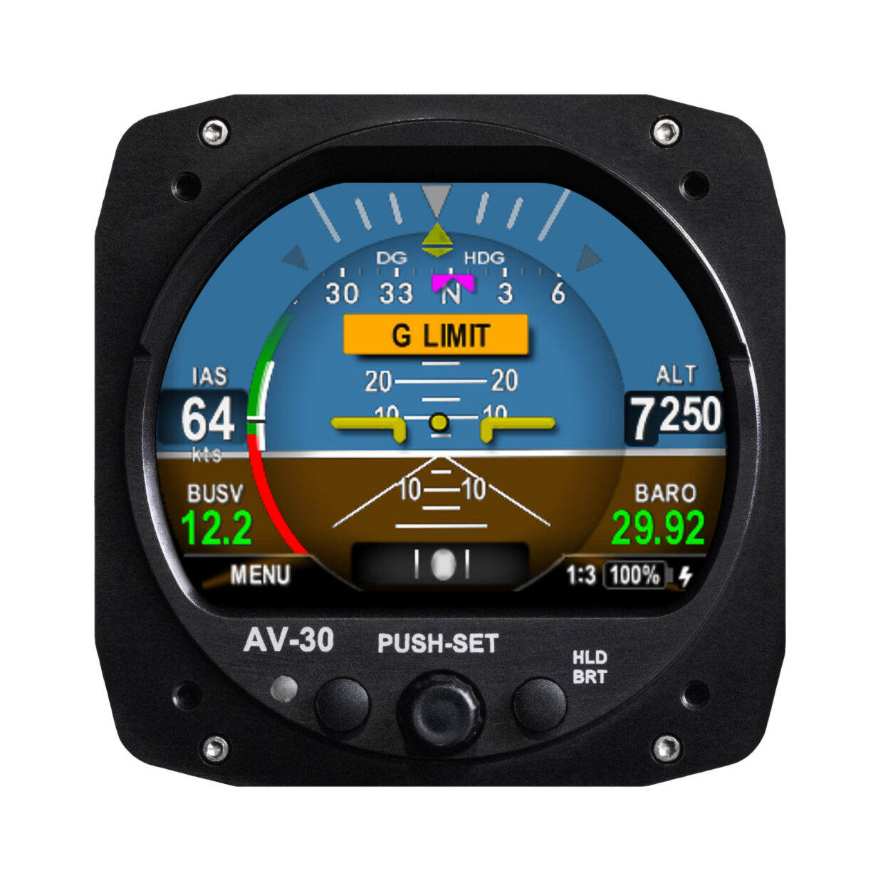
- Primary Attitude (AI Mode)
- Primary Slip (AI Mode)
- Primary Direction of Flight Indication (DG Mode)
Supplemental Functions:
- Indicated Airspeed
- Altitude
- V-Speeds
- Angle of Attack
- Vertical Trend
- Vertical Speed
- Set Altitude
- Heading
- Bus Voltage
- G Load
- Outside Air Temp
- True Airspeed
- Density Altitude
- GPS Navigator Waypoint Data
- GPS Navigator Nav Data
- GPS Navigator Route Line
- Heading Bug
- MFD Traffic Page with AV-Link
- Transponder Control (AI / DG Mode)
- Audio and Visual Alerting Functions:
- AoA Alerting
- G Limit Alerting
- Excessive Roll Alerting
- Set Altitude Alerting
- Carbon Monoxide Alert with AV-Link and Sentry
- AV-HSI integration with IFR capable equipment
- AV-APA integration with STEC autopilots
- AV-Link / ADS-B IN Traffic display with VSI indicator
- CDI display
- Rate of Turn indicator
- Standard Rate Bank angle indicator
- Rate of Climb (Feet/NM)
- G-Min/G-Max display
Miscellaneous Functions:
- Internal Battery Operation
- Auto / Manual Brightness
-
Does the AV-30 integrate with autopilot systems?
-
What level of GPS integration is supported?
The AV-30 provides an RS-232 receive line for “aviation” or “moving map” output provided by virtually every panel mount GPS navigator in service. This data is broadcast by the GPS navigator and no data is sent from the AV-30 back to the GPS unit. NMEA is also supported, which is output by most hand-held GPS units. NMEA protocol supports baud rate speed of 4800 and 9600, while “Aviation/moving map” protocol is fixed at a 9600 baud rate.
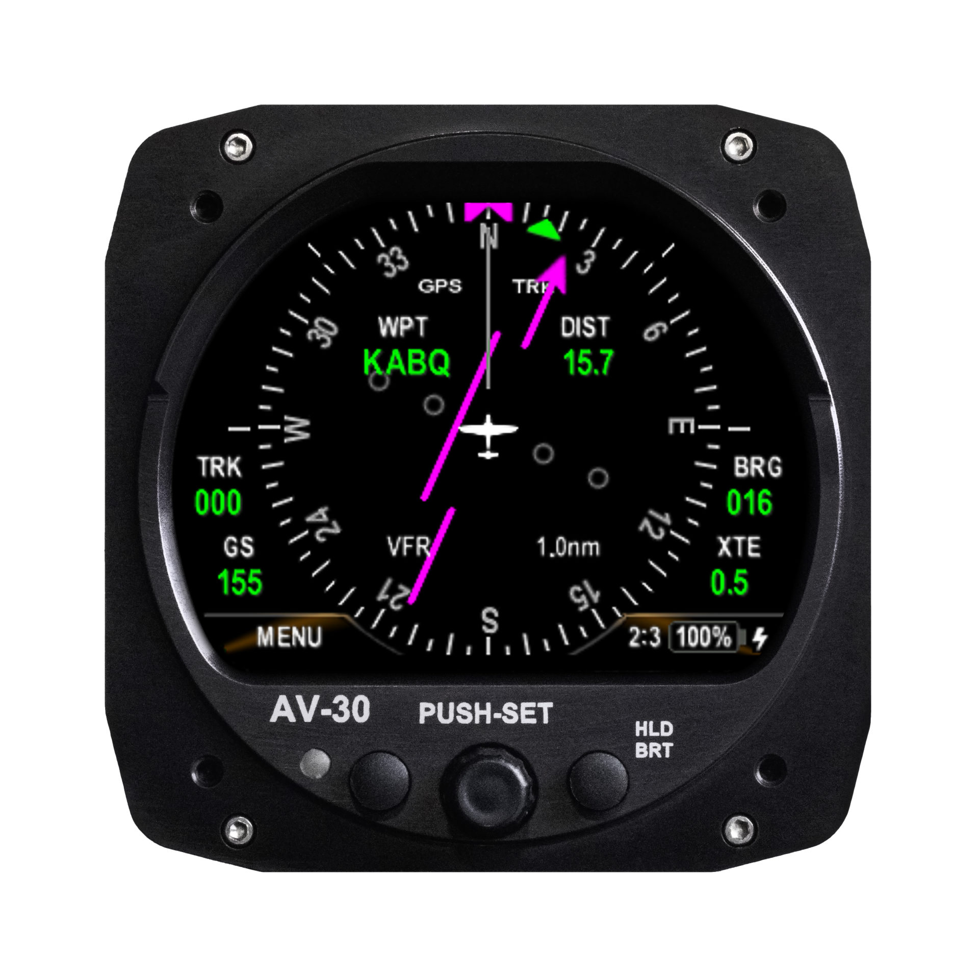
When connected to an external GPS navigator or hand-held, AV-30 operates as a repeater display. The data provided includes current waypoint ID, distance to destination, ground speed, cross-track error, desired track, and bearing to waypoint.
This data can be overlayed in the textual fields as desired and is used to create the compass rose (GPS Track), moving map display (ARC Mode), and create the GPS HSI presentation when the AV-30 is operating as a DG instrument. When operating as an attitude indicator, it can drive the direction tape and provides a bearing-to indicator.
The AV-30 now supports vertical navigation display with a connected AV-HSI. This will display IFR navigation information from an IFR navigator and digital NAV units.
-
Is AV-30 approved for primary IFR navigation?
When connected to an AV-HSI PMA and IFR-approved NAV/COMM or GPS Navigator, the AV-30 can be used as a primary display of navigation guidance.
-
How does the AV-Link PMA expand the AV-30's functionality?
The AV-Link PMA enhances the AV-30’s capabilities by:
- Providing live ADS-B traffic for display on the AV-30 traffic page
- Enabling wireless firmware updates of the AV-30
- Offering future connectivity enhancements through the latest firmware and software innovations
AV-Link PMA is available for both certified and experimental aircraft.
If installed with an AV-HSI the AV-Link can be connected to the AV-HSI for communication of all units that are wired to the AV-HSI.
-
How is “Probeless”Angle of Attack Determined?
Angle of attack is determined by comparing aircraft pitch to the actual flight path angle through the air. This is equivalent to the angle at which the wing is intercepting the body of air surrounding the aircraft – exactly the same as a probe based AoA system. Pitch is determined by a precision internal AHRS, and flight path angle is determined by a precision ADC (airspeed and vertical speed). The resulting angle is then augmented with G-Load, as determined by internal acceleration sensors.
For example, during a climb, if the pitch angle is 10 degrees up, and the aircraft’s flight path through the air (forward airspeed and vertical speed) is also 10 degrees up, the equivalent AoA is 0 Degrees. However, if the flight path angle through the air is only 7 degrees, then the equivalent AoA is positive 3 degrees as the wing is no longer able to maintain full lift.
Therefore, no dedicated AoA probe is required – only internal inertial and pressure sensors (8 in total). Connection to the aircraft’s pitot static system is required.
Reference Sperry Patent #3,948,096 for additional implementation details.
-
Does the Probeless AoA behave exactly like the probed system?
Yes and no. During the majority of flight conditions, they are equivalent. However, during conditions where the aircraft is moving through a mass of air that has a vertical component, the behavior is slightly different.
As vertical updrafts are rarely of concern, the scenario to look at is the downdraft during final approach. In this environment, the aircraft will sink at a rate that is not consistent with the aircraft pitch. As the algorithm utilized compares the aircraft pitch to the actual flight path through the air, this will result in an artificial positive AoA (see diagram).
A downdraft that forces a sink rate of -1000 FPM will effectively increase the current AoA by approximately 5.6 degrees (this is speed dependent).
In effect, this makes the AoA thresholds more sensitive and an alert will be generated earlier than normal – but that’s a good thing in this scenario.
If a down-draft of this magnitude is experienced, the pilot action is to add power; Similarly, if AoA exceeds the configured limit, the pilot action is also to add power. As the pilot actions are identical for both scenarios, it can be argued that the source of unexpected altitude loss (downdraft or a wing losing lift) is irrelevant. Add power.
Interestingly, if taken to the extreme, the probeless AoA system actually starts to behave like a wind-shear alerter and any downdraft that is sufficient to cause excessive pitch vs flight path angle will generate an alert – it’s effectively a sink rate alert at that point.
In a probed system, as the probe is only measuring ambient air angle and loss of altitude is not measured, this arguably advantageous behavior is not available.
-
Does the AV-30 support a magnetometer?
Yes.
For more information on uAvionix AV-Mag PMA.
-
-
-
How do I update the AV-30 firmware?
Firmware updates for the AV-30 can be performed wirelessly using the AV-Link. Instructions are provided with each Service Bulletin. This video demonstrates an update to the AV-30.
-
What are the recommended maintenance practices for the AV-30?
Please follow the Instructions for continued airworthiness found on our website
-
-
-
What should I do if my AV-30 isn't displaying data correctly?
Please visit the support page for more guidance on common issues.
-
- Contact Support: If the problem persists, reach out to uAvionix support for assistance.
-
-
-
-
Where do I find the latest Software Update or Service Bulletin?
Please look at the support page for the AV-30-C.
and for the AV-30-E
-
Documentation
AV-30 Manuals and Guides
General Documentation
STC Documentation
AV-30-C Installation Manual UAV-1003947-001 [ Revision R – 2/23/26 ]
AV-30-C Approved Model List (AML) SA00410BO
AV-30-C Instructions for Continued Airworthiness UAV-1004045-001 [ Revision E – 3/27/25 ]
AV-30-C Pilots Guide UAV-1003946-001 [ Revision L – 2/23/26 ]
AV-30-C Flight Manual Supplement UAV-1004044-001 [ Revision E – 5/21/25 ]
AV-30-C FAA STC SA00410BO [ Revision 05 21 2025 – 5/23/25 ]
AV-30-C Master Drawing List UAV-1004236-001 [ Revision AD – 2/23/26 ]
AV-30-C Permission to Use FAA STC UAV-1004535-001 [ Revision A – 8/31/20 ]
STC International Validation
AV-30-C Transport Canada Civil Aviation STC SA21-52 [ Revision 2 – 10/24/25 ]
AV-30-C Permission to Use Transport Canada Civil Aviation STC UAV-1004535-004 [ Revision A – 9/29/21 ]
AV-30-C UK CAA STC 00069 [ Revision 1.0 – 4/6/21 ]
AV-30-C Permission to Use UK-CAA STC UAV-1004535-003 [ Revision A – 5/20/21 ]
AV-30-C EASA STC 10075856 [ Revision 1.0 – 5/18/21 ]
AV-30-C Permission to Use EASA STC UAV-1004535-002 [ Revision A – 3/17/21 ]
AV-30-C Brazil STC 2022S01-10 [ Revision 1.0 – 1/24/22 ]
AV-30-C EASA Minor Change Robin Aircraft 10078225
AV-30-C Permission to Use Brazil STC UAV-1004535-005 [ Revision A – 1/24/22 ]
AV-30 Mexico STC (Convalidación IA-1003-2025 del STC SA00410BO)